


The writer's feel that most aeromodellers are put off Neutral Point and Static Margin theory because they feel the subject is too technical and of little real use as they are confident of where to locate the Center of Gravity in their aircraft anyway. The purpose of this article then, is to enable the reader to get a real understanding of Neutral Point and Static Margin and so make a decision as to whether to use the knowledge for their own aircraft.
To get an understanding of these concepts, readers first need to understand two technical concepts, (i) Stability and (ii) Moments.
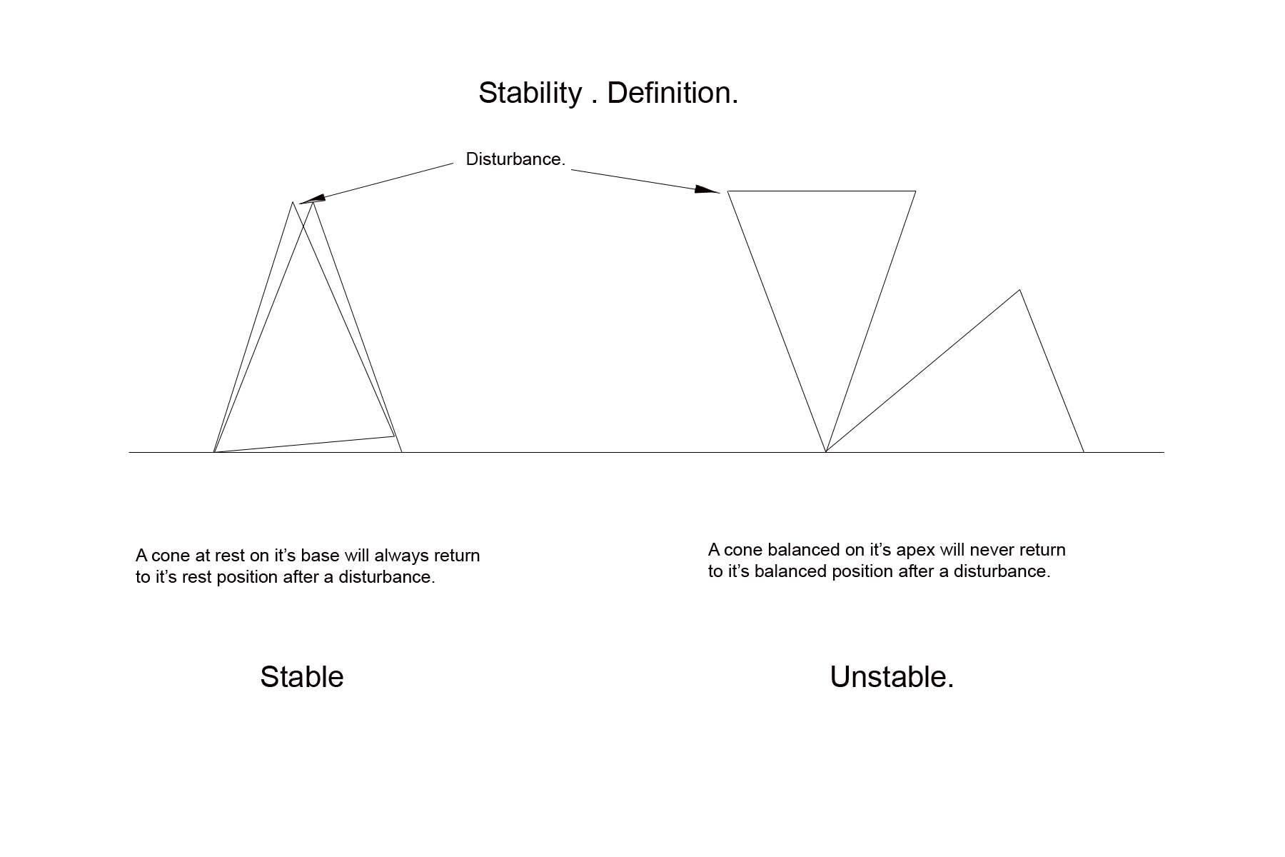
(i) Stability.
The diagram below gives a technical description of stability which is directly analogous to the stability of an aircraft.
(ii) Moments.
Diagram 1 below uses moments and will be self exaplanatory.
Probably the best way of visualising Neutral Point is with the analogy of the see-saw in the playground.
The See Saw as an analogue of Neutral Point and Static Margin.
Diagram 1.
Shows a see saw with two identical weights of 10 lbs. at each end, balanced horizontally.
Total length of the see saw is 20 ft., i.e. 10 ft. each side of the fulcrum.
Everybody reading this will know that the see-saw is in perfect balance, i.e. once set up at any angle, the see saw will not move. It has zero stability in that it will not return to it's original position once disturbed.
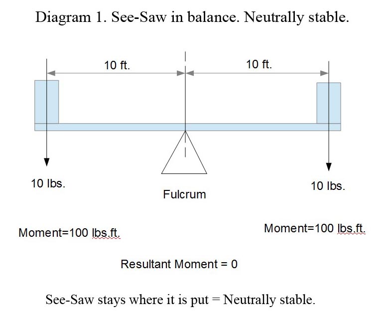
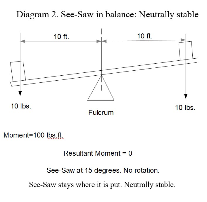
Diagram 2.
Shows a see-saw with two identical weights of 10 lbs. at each end, balanced at an angle of approx. 15 degrees.
Neutral Point and Static Margin of an aircraft.
Diagram 3.
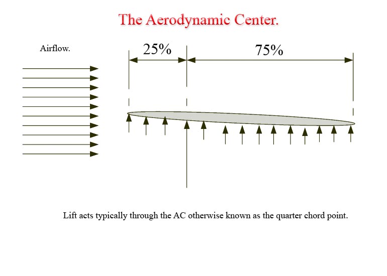
Diagram 3 shows that when a wing is in airflow the lift generated is spread over the whole flying surface. The small arrows represent the milions of force vectors acting over the flying surface creating the lift.
The point at which the resultant force vector acts, (represented above by the larger arrow), is the Aerodynamic Center of the wing.
The wing chord used is the MAC or Mean Aerodynamic Chord, as this concept allows for all wing planforms to be considered. The planform is the shape of the wing layout when looked at in plan view, i.e. from above. This means that the theory can be applied to any wing, e.g. delta, sweep back, tapered etc., once the MAC has been calculated for the wing concerned.
Wind tunnel work shows that the aerodynamic center of a wing is typically 25% of the mean aerodynamic chord, or MAC.
Conventional fixed wing aircraft have two wings, i.e. the main wing, and a smaller wing, the stabiliser, referred to as the tailplane here in the UK.
Diagram 4.
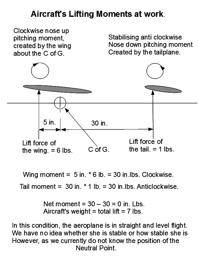
Diagram 5.
The important point here, is that Neutral Point and Center of Gravity are two separate concepts. Neutral Point is nothing to do with the weight or CG of the aeroplane, but rather is entirely about the aeroplane's planform, i.e. the aeroplanes wing and tail surface area and aspect ratio. The reason this is so, is because the resulting moments created by the wing and tailplane result from airflow over aerofoils which create pressures and thereby forces, in this case lift, i.e. nothing to do with weight.
If you have followed the diagrams through, this separation should be clear. To be certain however, we can add this:
If the aeroplane is given ballast weight at the nose the CG will move towards the nose and vice versa. Regardless of where the the CG is however, the neutral point does not move. To change the the position of the Neutral Point, we need to change the aircraft's design, e.g. by increasing or decreasing the tailplane's moment arm, increasing the tailplane's area or aspect ratio.
Note: Planform refers to the aircraft's shape when looked at from above, e.g. wingspan, wing chord, sweepback, taper etc.
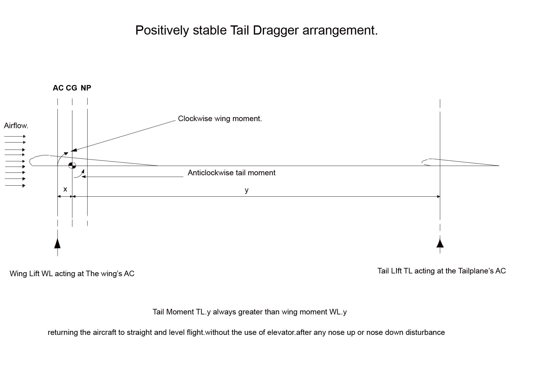
All the foregoing leads to three readily identifiable states of stability for tail dragger aircraft. (Other configurations require small changes but the principles still apply):
1. Positive Stability. Neutral Point aft of the C of G. Means the aircraft will return to the position it was in before a disturbance pitched the aircraft up or down. Inherently stable. Aircraft will self correct after a disturbance without pilot input.
2. Neutrally Stable. Zero Stability. Neutral Point at the C of G. Means the aircraft will not return to the position it was in before a disturbance pitched the aircraft up or down. i.e. if pitched down it will stay pitch down unless corrected by adjusting the tail moment, e.g. by pilot input adding up elevator. Extrememly difficult to fly. Normally requires computer assist.
3. Negative Stability. Unstable. Neutral Point forward of the C of G. Means the aircraft will not return to the position it was in before a disturbance pitched the aircraft up or down but will rather further diverge from it's original position. Negative Instability of this kind is uncontrollable. A good example of aircraft in this state is Tucking In.
This leads to the realsation that the further the Neutral Point is aft of the C of G, the greater the inherent stability of the aircraft in the pitch axis which in turn leads to the concept of Static Margin. The analogue equivalent in our cone example of stability above is: the broader the cone's base, the more stable it becomes, i.e. the more quickly it returns to to rest position after a disturbance.
The distance between the C of G and Neutral Point is known as the Static Margin, which is expressed as a percentage of Mean Aerodynamic Chord
All this leads to a very worthwhile point:
A starting point for our maiden flights should typically be around 10% Static Margin. If we ensure this is met by using Neutral Point software available in RCAeroBase, (article 3 below) and adjusting the CG to match, or by using The Winning Formula, (article 2 below to find the CG position for ten percent SM), then we will have no surprises with pitch axis instability on our maiden flights.
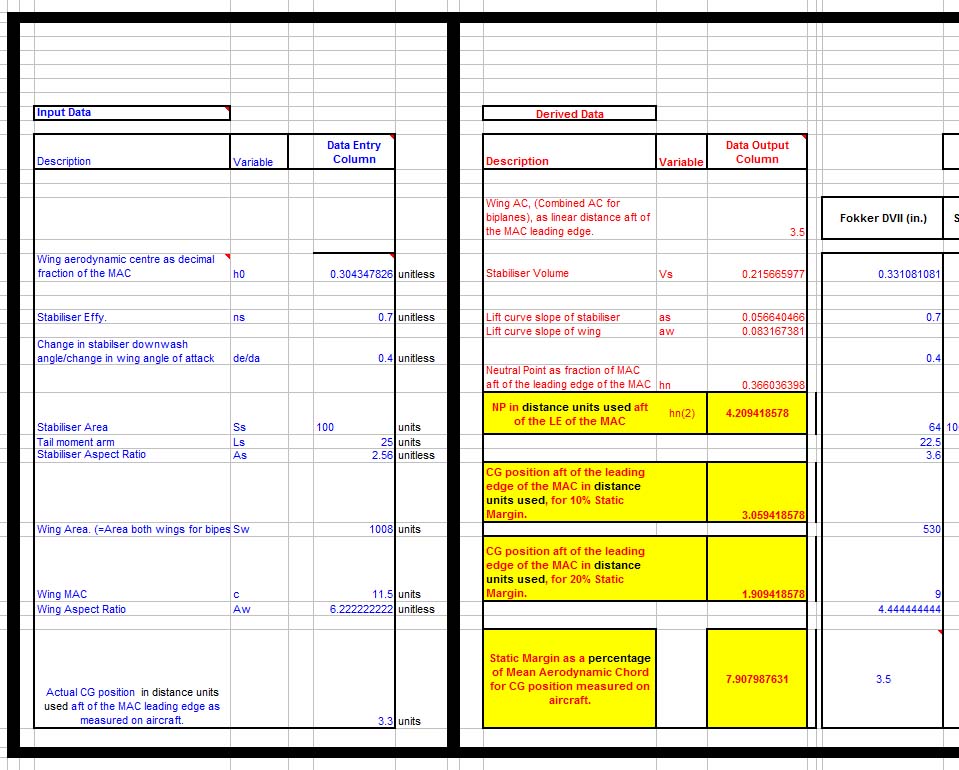
Output of Neutral Point Software.
Note: The software is available via DropBox in the article but users may request the software as an Excel file by sending a request comment to RCAeroBase after registering at the site.
Related Articles:
Neutral Point and Static Margin. 1. Visualisation.
Neutral Point and Static Margin. 2. The Winning Formula.
Neutral Point and Static Margin. 3. Software.
Neutral Point and Static Margin 4. Tucking In
Neutral Point and Static Margin. 5. Stall On Landing Approach
Neutral Point and Static Margin. 6. Aircraft unstable about the Pitch, or lateral Axis.
Comments
7th. July 2017.
Currently under review for minor edits which will be detailed shortly.
Updated Diagram 5.
Added the output of Neutral Point Software.
Expanded the text to give more clarity.
Added the diagram on stability as a technical concept.