


Disclaimer
While every effort is made to ensure that the data presented here is accurate the writers cannot take responsibility for any errors, or consequences from those errors, that may occur. Ultimately the sole responsibility for all aspects of safety rests with the aeromodeller.
The disclaimer above is generic to all articles on this website and is shown on our Home page, but given that errors in the charging of lithium Polymer batteries can lead to such serious consequences we would add the following special notes to the disclaimer for this specific article.
All readers and users who use this article to explore the parallel charging method should ensure they protect themselves from injury and their property from damage that could result from errors or any unforseen issue. Ultimately the sole responsibility for all aspects of safety rests with the user.
Cause:
There are various causes for this uncertainty e.g. lack of experience with electrical circuits and terminology.
Fix:
This RC AeroBase article with it's in depth text, photos and videos, focuses on the parallel charging of Lithium Polymer battery packs, covers all aspects of the process and should answer most questions about the charging method. In addition the article emphasises recommended best practice safety.
Comment:
The process if executed well, offers great time savings for model pilots that use electrical power systems.
Summary:
1. Technical knowlege needed.
2. The Parallel Charging Process step by step.
3. Pros and Cons.
4. Safety.
5. What to avoid and why.
6. What can go wrong and how to avoid it.
6a. Checking the new paraboard for shorts before use.
7. Video 1. Charge Equalisation.
8. Video 2. Current sharing in a parallel circuit during the charge process.
9. Video 3. The Process.
10. Bibliography:
1. Technical knowlege needed
From a technical perspective the user ideally needs some elementary knowledge of electrics in particular:
Ohm’s law
V = I x R
Where:
V is the potential applied to a circuit, which is measured in volts.
I is the current flowing in the circuit, measured in amperes. (amps)
R is the resistance of the circuit measured in ohms.
From this law we can derive:
P=V x I
Where:
P is the power developed in the circuit, measured in watts. (Please note the simple formula is for dc resistive circuits but is all we need for our purposes here.)
Kirchoff’s Law
This law says that the algebraic sum of currents at a junction equals zero, and explains why a parallel circuit of identical loads will share the current fed into the junction equally.
While it is not necessary to have a detailed understanding of this stuff, it is necessary to be able to manipulate the equations a little, as unlike charging a single LiPo pack where the digital charger is designed to do everything for the user providing he reads the charger’s instructions, paraboard instructions are often non existent.
That said there are three calculations the user needs to be able to perform confidently:
i.) Setting up the charger.
Example:
Let us say the user has a requirement to charge six 2200mAhr 3S LiPos on one Paraboard at a charge rate of 1C
So, how should the charger be set up?
From Kirchoff we need 6 x 2.2 amps. = 13.2 amps as the charger output current, so the charger parameters need to be:
3S; Balanced Charge; Current 13.2 amps.
This total current is fed into the Paraboard and is split 6 ways ensuring each LiPo pack receives 2.2 amps. I.e. each LiPo pack is charged at 1C generating no heat, and ensuring that the charging process will take one hour or less, approximately.
ii.) Choosing the charger(s):
LiPo individual cells have a nominal voltage of 3.7 volts, so three cells connected in series, (3S), have three time this i.e. 11.1 volts.
For this requirement then of charging six 2200mAhr 3S LiPos on one Paraboard at 1C, the charger power output needs to be 11.1 x 13.2 = 147 watts. In fact more than this is needed if you take into account losses etc. The point being if you rush out and buy an 80 watt budget charger it will not be able to charge the packs at 1C. In this case nearer to 0.5C and bearing in mind you cannot leave the charging process for safety reasons, the longer time spent in the workshop could be prohibitive.
This said the user could well need multiple chargers and paraboards so that an entire fleet's battery packs can be charged within one hour in the workshop. If this is the case then the user will need to consider power supply choice carefully.
iii.) Choosing the Power Supply:
The power supply used must be able to meet the worst case charging requirements of the user with some additional headroom.
For example if the fleet to be taken to the flying field contained three aircraft using the battery types above then the total power needed is three time the above, i.e. 3 x 147 = 441 watts, so the user needs three chargers, three paraboards, and a 500 watt charger.
The trick is always to think in terms of power, (watts), and not current, (amps). To make this clear, 10 amps at 3 volts needs 30 watts, whereas 10 amps at 12 volts needs 120 watts.
All this said, this is as complicated as the tech stuff gets.
2. The Parallel Charging Process step by step
While most types of battery packs can be charged when connected in parallel, this article is concerned with the parallel charging of the mainstay of the model pilot's primary power source packs, i.e. the Lithium Polymer.
That said, the basic principles behind the approach shown here can be used for other battery types.
| Step | What | How | Detail | Why |
| 1. | Equalise the charge level of the LiPo packs to be charged on the paraboard. | Connect the power leads of the LiPos to the paraboard only, leaving the balance connectors disconnected. |
This parallel connection of power leads allows equalisation currents to flow between the packs as the battery packs with higher levels of charge transfer that charge to the packs which have lower levels of charge. This process is automatic and self regulating and benign as the currents, (amperes), which flow are well within the packs current limits. While the initial currents which flow in this part of the process can be somewhat high depending on the difference in charge level, they quickly reduce in magnitude as equalisation proceeds. Avoid equalising packs that have a difference in state of charge which is greater than 25%. This ensures that the equalisation currents which flow are not excessive. Ensure the paraboards power rating matches the charge process being undertaken. This is usually dictated by the power connectors the manufacturer uses. In this case the paraboard used has a rating of 60 watts and uses XT60 power connectors. |
This ensures that charge transfer does not pass through the LiPo pack balance leads which are designed for low currents only and initial charge equalisation currents could exceed their ratings. |
| 2. | Charge the LiPo packs connected to the paraboard. |
Connect the balance leads of the packs to the paraboard, so that power leads and balance leads are both connected. Connect the assembled paraboard and LiPos to the charger. |
Set the charger parameters, viz: Battery type: LiPo. Pack config.: e.g. 3S Current level: e.g. if 4 x 3S 2200 mAhr Lipos are connected to the paraboard, the charger output current to be set is four times the 1C rating of each pack, namely 4x2.2 amps = 8.8 amps. Begin charging. |
This ensures that the current taken by each LiPo pack in the paraboard is always 1C, (which means no heat will be generated), in this example 2.2 amps per pack. Please note charging at above 1C is possible but it not covered here. |
| 3. | Double check the charger parameters entered are correct. | Errors in setting up these values can lead to overcharging. | ||
| 4. | Ensure that the charging process is carried out in a recommended best practice steel enclosure. (See the video) | Using a steel enclosure with a hinged lid which can be locked as in the videos is one example that meets the recommended best practice standard. |
This means that should the worst happen, a LiPo flare will be contained without damaging property or the person managing the charging process. While a risk assessment of a flare occurring in practice will be very low provided the user makes zero errors in his setup, should the worst occur, you are not looking at one pack connected to a charger but six in the the example given, so the consequences of a flare could be very serious indeed and the user carries the responsibility to take every precaution to ensure that does not happen. |
|
| 5. | Start the charge process and monitor at regular intervals. | Periodically inspect the packs at intervals of say fifteen minutes to ensure all is proceeding well checking temperature of the packs and balance leads which should show no temperature rise above ambient. | Should anything go wrong, e.g. a LiPo pack go open circuit during the process, thus increasing charging currents in the other connected packs, temperature rise is the first thing that would occur. (Note in the four by 3S example given above 8.8 amps shared by three packs would raise the input current per pack from 2.2 amps to 8.8/3 = 2.93 amps.) | |
| 6. | Supervise the charging process at all times. | Periodic timed inspection. | Use a simple timer. | The person charging the packs needs to have constant eyes on the process for reasons of safety. |
| 7. | Should anything untoward occur, disconnect power, ensure the steel enclosure is locked and execute the safety plan. | It is always a good idea to have a safety plan. This is dependant on many factors and is up to the user to organise and implement. |
3. Pros and Cons
| Pros | Cons |
| The process is fast and can offer great time savings to model pilots who fly electric powered aeroplanes. | The greater the number of LiPos charged simultaneously, the greater the risk of something going wrong and the greater magnitude of consequences should the worst happen. This means, as always, the user must have eyes on the process at all times and be able to interrupt the process competently and safely and at a moments notice. |
| The process is robust provided recommended best practice safety is followed. | There is no room for error. Should an operator make errors with his charging parameters or not fully understand what the parameters set really mean, then this could lead to overcharging and flares. |
| Any number of LiPos can be charged within one hour at 1C provided the user has multiple chargers of adequate power rating, multiple paraboards of adequate power rating, and a big enough dc power supply to power everything connected. |
4. Safety
Please remember a Lithium Polymer battery flare is a potentially lethal event and life changing injuries and house fires resulting from them are already on the record.
WARNING do not proceed unless you have the necessary competencies.
Please remember safety is the sole responsibility of the model pilot.
Given the above, the table below addresses important aspects that should be avoided if the process is to meet recommended best practice safety standards.
5. What to avoid and why
| Avoid | Why | Detail |
| Mixing chemistries. |
Overcharging could occur. Temperature rise could occur. |
For example Lithium Polymer, (LiPo), has a nominal voltage of 3.7 volts per cell. Lithium Iron Phosphate, (LiFe), has a nominal voltage of 3.3volts per cell. Charging these two chemistries in parallel would mean that voltages that would correctly charge the LiPos could overcharge the LiFes and damage them. |
| Mixing pack types. 2S, 3S, 4S etc. |
Overcharging could occur. Temperature rise could occur. |
For example if 2S and 3S packs were mixed on the paraboard, the 2S packs would see too high a voltage during the charging process and be damaged. |
| Connecting balance leads during equalisation. | Balance leads and paraboard tracks can be damaged. |
The user needs to avoid driving high currents through delicate balancing circuitry. This could easily happen if the balance leads were connected during equalisation thereby damaging the the balance leads and their associated circuitry. Ensure the state of charge of the packs to be charged in parallel are equal after the equalisation process by metering them before beginning the charge process. |
| Equalising packs with widely differing levels of charge, (>25%), at the start of the charging process. |
Initial equalisation currents can be high. This is minimised if the charge states are similar when charging starts.
|
Normally this presents no problem as the user will typically have say six battery packs per aircraft. These are used in the air on a timer and so will be fairly close in charge state after flight. Massive charge discrepancies can be dealt with separately by partially discharging the higher charged packs on the charger/discharger before connection to the paraboard. |
| Charging packs with differing charge capacities. |
C ratings could be exceeded. Temperature rise could occur. |
For example, if two 3S packs are to be charged in parallel, where one has a capacity of 2200 mAhr, and the other a capacity of 1100 mAhr, then by setting the charger output current to 2.2 amps to charge the 2200mAhr pack at 1C, the 1100mAhr unit would also take 2.2 amps in it's paralled position, i.e. it would be charged at 2C The whole approach in this AeroBase article is to avoid all temperature rise during charging by charging all packs at 1C. All that said, this is generally not a problem, as the user will typically have a set of identical battery packs for a given aircraft, which will fill a six pack paraboard. |
| Charging packs in parallel that show deterioration in charge capacity which can occur as packs age | Overcharging could occur. | Typically this not a problem as the user monitors the process at all times as it takes typically one hour. This monitoring means that anything untoward is spotted early, allowing the user to investigate any problems after stopping the charge process. |
6. What can go wrong and how to avoid it.
Please note, where necessary the following points are expanded after the table.
| Problem | Cause. | Fix. | Comment. | |
| 6a.) | New paraboard could have shorts. | Manufacturing process failure. |
1. Remove rear insulation from the paraboard exposing the printed circuit board tracks. 2. Locate and remove any shorts exisiting between tracks. 3. See detailed method below. |
Quality control limitations or strategy can lead to this problem. Risk level is considered low if optimised process followed and in particular: a.) Using a recommended best practice safety enclosure for the charging process. b,) Constant implementation of the user's battery charging safety plan. |
| 6b.) | LiPo Packs could go open circuit while charging. |
1. Manufacturing process failure. 2. Heavy landing could weaken the LiPo assembly, leading to an open circuit state. |
1. Meter all packs: a.) before equalisation. b.) before charging. c.) after charging.
|
This thorough approach to checking the packs will in most cases preclude the possibility of connecting a LiPo pack to the paraboard for charging which has open circuit. Should the open circuit occur while charging however, then the continual eyes on the process aproach should prevent an adverse situation. i.e. any temperature rise alerts the operator to stop the process. Risk level is considered low if optimised process followed and in particular: a.) Using a recommended best practice safety enclosure for the charging process. b,) Constant implementation of the user's battery charging safety plan.
|
| 6c.) | LiPo Packs could go short circuit while charging. |
1. Manufacturing process failure. 2. Heavy landing could weaken the internal structure LiPo assembly, leading to a near short circuit state. Charging in this damaged state could set the short, which would then rapidly worsen. |
1. Meter all packs: a.) before equalisation. b.) before charging. c.) after charging. Should this occur while charging a flare could occur.
|
The user is protected from the consequences of this eventuality by using a recommended best practice enclosure for the charging process and their battery charging safety plan. Risk level is considered low if optimised process followed and in particular: a.) Using a recommended best practice safety enclosure for the charging process. b,) Constant implementation of the user's battery charging safety plan. |
| 6d.) |
The equalisation process could damage the power tracks of the paraboard and exceed the C rating of the packs.
|
1. Difference in the state of charge of the packs connected exceeds 20% thus driving heavier currents at the start of the equalisation process. 2. Incorrectly rated paraboard used.
|
1. Before paraboard equalisation is tried, ensure that the the difference in the state of charge of the packs connected does not exceed 20% 2. Check the temperature of the paraboard track at the start of the equalisation process. 3. Stop the process if any significant temperature rise is noted and recheck the state of charge of the LiPo packs. |
Considered unlikely to occur in practice if optimised process is used. The backup safety is as always the recommended best practise enclosure. Risk level is considered low if optimised process followed and in particular: a.) Using a recommended best practice safety enclosure for the charging process. b,) Constant implementation of the user's battery charging safety plan. |
| 6e.) | The equalisation process could damage the balance tracks of the paraboard and the balance wiring of the LiPos | LiPo Balance connectors connected to the paraboard before equalisation of charge state has been carried out. |
Always equalise charge states of LiPos by connecting the LiPo power connectors only to the paraboard. Connect the LiPo balance connectors to the paraboard after the equalisation process is completed. |
Failure to attend to this point will probably damage the connected LiPo's balance leads and paraboard. Risk level is considered low if optimised process followed and in particular: a.) Using a recommended best practice safety enclosure for the charging process. b,) Constant implementation of the user's battery charging safety plan. |
| 6f.) | The parallel charge process could damage the balance leads and their associated circuitry. | Parallel charging before the LiPo packs have been equalised and have reached an equal state of charge. | Meter all packs after the equalisation and do not proceed to charging if equalisation is incomplete. |
Considered unlikely to occur in practice if optimised process is used. Risk level is considered low if optimised process followed and in particular: a.) Using a recommended best practice safety enclosure for the charging process. b,) Constant implementation of the user's battery charging safety plan. |
| 6g.) |
Short circuit of the LiPos connected to the Paraboard could occur. Note:While this is a generic problem not confined to parallel charging, the magnitude of the short circuit currents which could occur is considerably greater with parallel connected LiPos and so the point is included. |
Flying lead connections made in the wrong sequence thus allowing short circuits to occur. Badly connected crocodile clips allowing short circuits to occur. |
Connect all charger leads in the charging circuit in an optimised sequence such that short circuit currents detailed at left cannot occur. |
If the sequence of connections carried out by the user is incorrect then all flying lead connections such as banana plugs and crocodile clips could easily lead to short circuits. Further if optimised process is not followed and the user leaves the process, then such a short circuit condition could be left undetected with serious consequences. Risk level is considered low if optimised process followed and in particular: a.) Using a recommended best practice safety enclosure for the charging process. b,) Constant implementation of the user's battery charging safety plan. |
6a. Expansion.
New paraboard could have shorts.
Ensuring that Paraboards are fit for purpose before using.
Commercially available paraboards for parallel charging of LiPos are now available and are a boon in the way they simplify the process for the operator. That said it must be borne in mind that they are a mass produced item and so regardless of the manufacturer's quality control processes, it is possible that the new paraboard you intend to use could be carrying unexpected short circuits. This can happen if the soldering process is not as good as it should be thereby causing tiny solder bridges across printed circuit tracks. If the user is unaware of such a manufacturing shorts and connects the charger to the circuit with batteries in place, then delicate LiPo balancing parallel tracks and wiring could be damaged and worse. For this reason the user should meticulously check the product before using. How this is done, is shown in the following photographs.
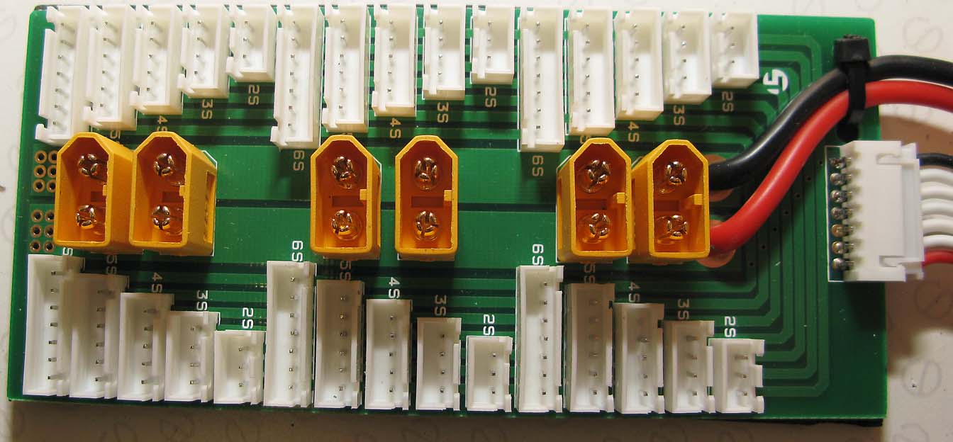
Paraboard Topside (Turnigy example)
The passive nature of the paraboard is clear in this view, i.e. no active components like transistors etc. Just a simple set of parallel connections.
The six XT60 power connectors with their heavy duty printed circuit tracks, (60 amps in this case), are clear to see running down the centre of the board.
The paralleled white JST XH connectors with their narrower printed circuit tracks run along both sides of the power connectors.
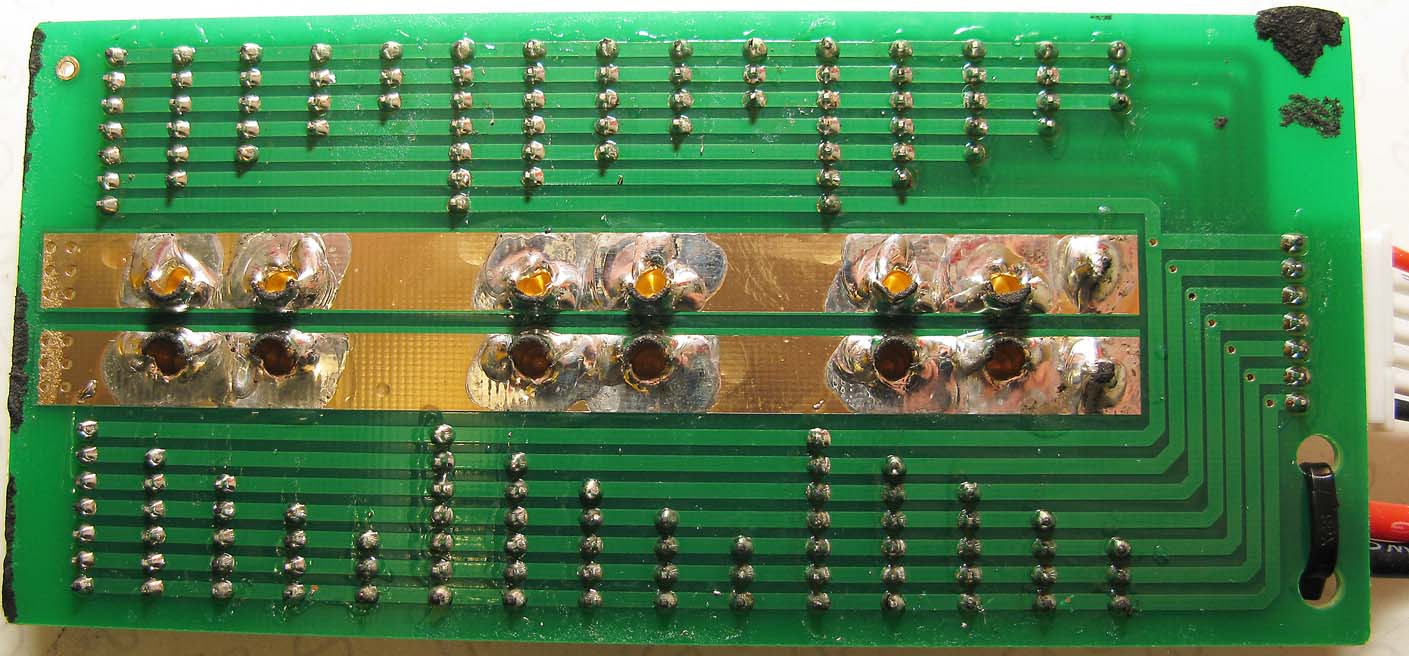
Paraboard Underside
To check for solder bridges and residual wiring strand shorts, simply remove the backing insulation and brush the circuit board with a good clean paintbrush, then view the tracks through a magnifier. While there is no need to expect the worst, should you find anything, you can remove the shorts before proceeding with the parallel charging process.
Refitting the backing insulation after inspection is easy to do.
6d.) Expansion.
The equalisation process could damage the power tracks of the paraboard and exceed the C rating of the packs.
There are conflicting views on this point, so these are addressed here.
Because initial equalisation currents can be high there is a need to know what the levels of current are so that users can assure themselves that charge and discharge currents that take place during equalisation do not exceed the pack's ratings. To explain this in detail the following four tests were made. The principle of the tests is that a source LiPo is connected in parallel to a load LiPo via a wattmeter. This allows data to be gathered in realtime so that tabulated data and graphs can be prepared to show the charge equalisation process in detail.
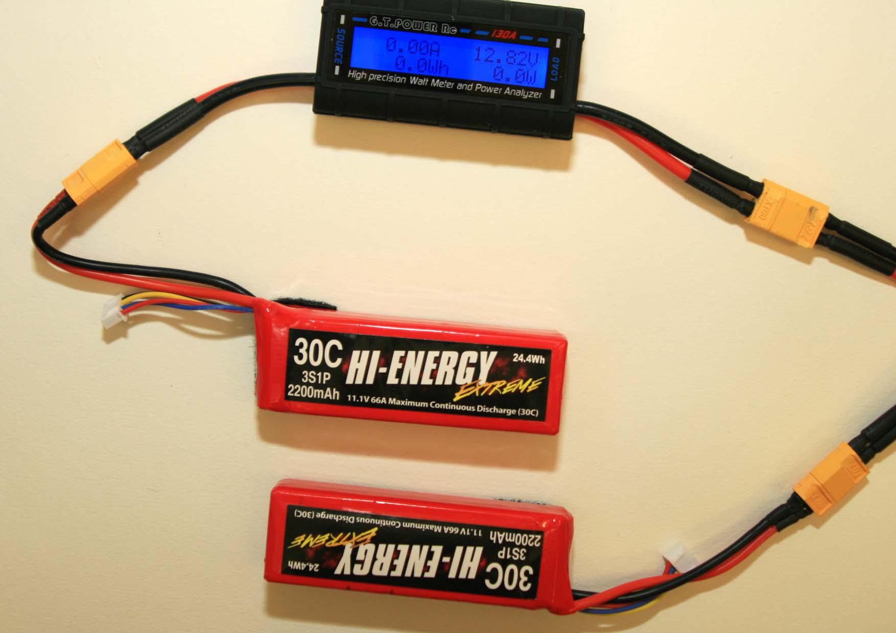
Circuit used for the tests:
Sample circuit shows a digital wattmeter and two 2200mAHr 3S LiPos after equalisation is complete, i.e. zero current is flowing.
At the start of the equalisation process, the Source LiPo is selected so that it's state of charge is always greater than the Load LiPo's state of charge allowing charging current to flow from the Source LiPo into the Load LiPo.
Test 1.
Two LiPos 1300mAHr 3s units used. Source LiPo charge state 99%, load LiPo charge state 80% Charge difference 19%, i.e. within the usually accepted guidelines for charge equalisation.
This initial test was run for fourteen minutes in order to reach zero equalisation current so that the full exponential current curve can be shown.
Subsequent tests are all run for a shorter period as it is the initial equalisation currents which are of interest given the risks outlined in the title of this section.
Data for test 1.
| Time. Secs. | Current. Amps. | Time. Secs. | Current. Amps. | Time. Secs. | Current. Amps. | Time. Secs. | Current. Amps. | Time. Secs. | Current. Amps. | Time. Secs. | Current. Amps. |
| 0 | 5.06 | 70 | 1.13 | 130 | 0.74 | 190 | 0.54 | 250 | 0.41 | 310 | 0.31 |
| 10 | 2.35 | 80 | 1.05 | 140 | 0.69 | 200 | 0.51 | 260 | 0.38 | 320 | 0.29 |
| 20 | 1.88 | 90 | 0.97 | 150 | 0.66 | 210 | 0.49 | 270 | 0.37 | 330 | 0.28 |
| 30 | 1.64 | 100 | 0.9 | 160 | 0.62 | 220 | 0.47 | 280 | 0.35 | 340 | 0.27 |
| 40 | 1.47 | 110 | 0.84 | 170 | 0.59 | 230 | 0.44 | 290 | 0.33 | 350 | 0.25 |
| 50 | 1.34 | 120 | 0.79 | 180 | 0.56 | 240 | 0.42 | 300 | 0.32 | 360 | 0.24 |
| 60 | 1.22 | ||||||||||
| 370 | 0.25 | 430 | 0.19 | 490 | 0.14 | 550 | 0.11 | 610 | 0.08 | 670 | 0.06 |
| 380 | 0.23 | 440 | 0.17 | 500 | 0.13 | 560 | 0.1 | 620 | 0.08 | 680 | 0.06 |
| 390 | 0.21 | 450 | 0.17 | 510 | 0.13 | 570 | 0.1 | 630 | 0.07 | 690 | 0.06 |
| 400 | 0.21 | 460 | 0.16 | 520 | 0.12 | 580 | 0.1 | 640 | 0.07 | 700 | 0.05 |
| 410 | 0.2 | 470 | 0.15 | 530 | 0.12 | 590 | 0.09 | 650 | 0.07 | 710 | 0.05 |
| 420 | 0.19 | 480 | 0.14 | 540 | 0.11 | 600 | 0.09 | 660 | 0.07 | 720 | 0.05 |
| 730 | 0.04 | 790 | 0.03 | 850 | 0.02 | 910 | 0.01 | ||||
| 740 | 0.04 | 800 | 0.03 | 860 | 0.02 | 920 | 0.01 | ||||
| 750 | 0.04 | 810 | 0.03 | 870 | 0.02 | 930 | 0.01 | ||||
| 760 | 0.04 | 820 | 0.03 | 880 | 0.01 | 940 | 0.01 | Total Minutes | 16 | ||
| 770 | 0.04 | 830 | 0.02 | 890 | 0.01 | 950 | 0 | ||||
| 780 | 0.03 | 840 | 0.02 | 900 | 0.01 | 960 | 0 |
Current curve for test 1
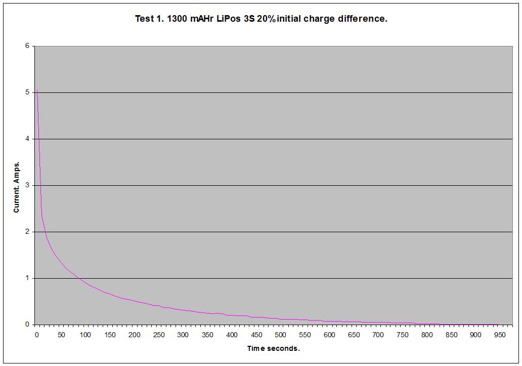
Conclusions from Test 1
The graph of the results table show the well known exponential current curve we would expect. While we are looking at batteries here, they, like capacitors, accept charge and deliver it, so there are no surprises in the curve.
The initial charge current of 5.06 amps recorded by the wattmeter exceeds the 2C specified maximum charge current given by the the manufacturer.
The value of excess is
(5.06 / (1.3 X 2)) = 2.03 times the rated value, or 203%
Because of the nature of the exponential curve however, the time for which this excess charge current exists is very brief indeed. After ten seconds it is already below the 2C threshold and is still declining rapidly. Because of this it is very unlikely in the writer's opinion that this transient excess charge current would trouble the battery.
It is important to add that electrical series connections within the pack will not be troubled in the slightest as they are discharge current rated, i.e. 30C in this case.
A last and most important point is that the 2C maximum charge current specified by most manufacturers of LiPo packs is a continuous rating i.e. the manufacturer is saying charging at 2C is perfectly OK for the entire charge cycle. The exponetial curve above shows the transient nature of the charge current taking place i.e. a much less arduous duty.
Data for test 2
| Time. Secs. | Current. Amps. | Time. Secs. | Current. Amps. | Time. Secs. | Current. Amps. |
| 0 | 6.22 | 70 | 1.29 | 130 | 0.78 |
| 10 | 2.83 | 80 | 1.2 | 140 | 0.73 |
| 20 | 2.16 | 90 | 1.09 | 150 | 0.68 |
| 30 | 1.92 | 100 | 1 | 160 | 0.64 |
| 40 | 1.73 | 110 | 0.93 | 170 | 0.59 |
| 50 | 1.57 | 120 | 0.84 | 180 | 0.56 |
| 60 | 1.44 | ||||
| 190 | 0.52 | 250 | 0.36 | 310 | 0.27 |
| 200 | 0.5 | 260 | 0.35 | 320 | 0.26 |
| 210 | 0.48 | 270 | 0.33 | 330 | 0.24 |
| 220 | 0.44 | 280 | 0.32 | 340 | 0.23 |
| 230 | 0.41 | 290 | 0.3 | 350 | 0.22 |
| 240 | 0.38 | 300 | 0.29 | 360 | 0.22 |
| 370 | 0.2 | ||||
| 380 | 0.19 | ||||
| 390 | 0.19 | ||||
| 400 | 0.18 | ||||
| 410 | 0.17 |
Current curve for test 2
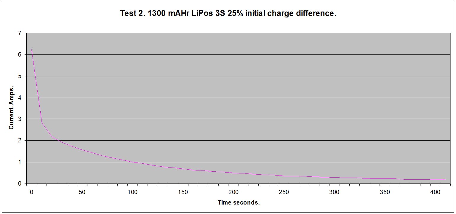
Conclusions from test 2
Charge current excess = (6.22 / (1.3 X 2)) = 2.39 times the rated value, or 239%
Time before 2C rating is achieved approximately = 15 seconds.
Data for test 3
| Time. Secs. | Current. Amps. | Time. Secs. | Current. Amps. | Time. Secs. | Current. Amps. |
| 0 | 6.72 | 70 | 1.73 | 130 | 1.09 |
| 10 | 3.47 | 80 | 1.61 | 140 | 1.01 |
| 20 | 2.61 | 90 | 1.49 | 150 | 0.94 |
| 30 | 2.37 | 100 | 1.37 | 160 | 0.87 |
| 40 | 2.17 | 110 | 1.27 | 170 | 0.8 |
| 50 | 2.02 | 120 | 1.18 | 180 | 0.74 |
| 60 | 1.86 | ||||
| 190 | 0.68 | 250 | 0.44 | 310 | 0.28 |
| 200 | 0.63 | 260 | 0.4 | 320 | 0.26 |
| 210 | 0.59 | 270 | 0.38 | 330 | 0.25 |
| 220 | 0.54 | 280 | 0.35 | 340 | 0.23 |
| 230 | 0.5 | 290 | 0.32 | 350 | 0.22 |
| 240 | 0.48 | 300 | 0.3 | 360 | 0.2 |
| 370 | 0.19 | ||||
| 380 | 0.18 | ||||
| 390 | 0.17 | ||||
Current curve for test 3
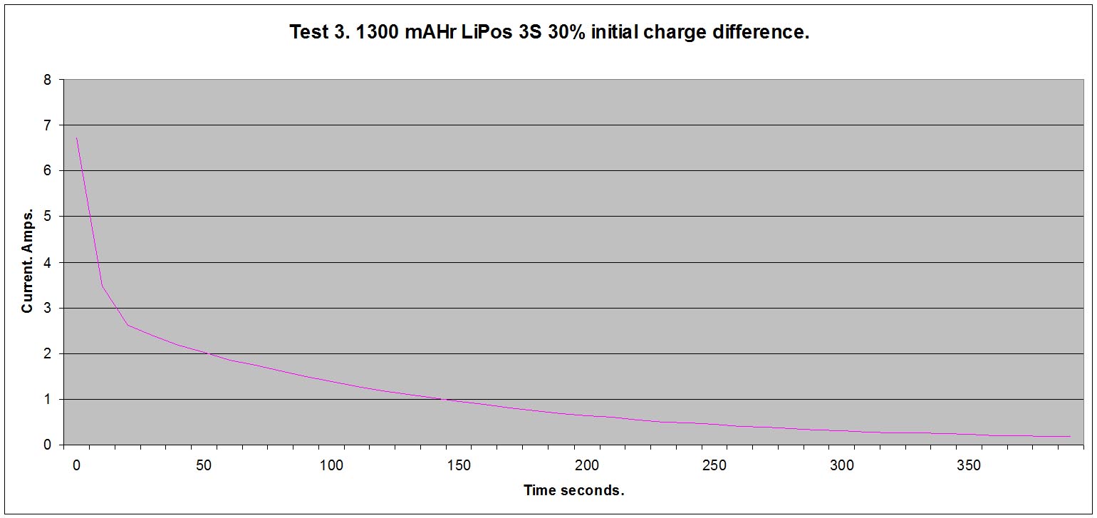
Conclusions from test 3
Charge current excess = (6.72 / (1.3 X 2)) = 2.58 times the rated value, or 258%
Time before 2C rating is achieved approximately = 20 seconds.
General conclusions.
Given the title of this section:
The equalisation process could damage the power tracks of the paraboard and exceed the C rating of the packs
20% charge difference would seem safe for most equalisation applications.
Higher levels of charge difference at the start of the equalisation process could well be acceptable in view of the the exponential nature of the charging current taking place. (citation needed)
7. Video 1. Charge Equalisation
The video shows the equalisation currents as they occur and how they decline as charge is shared between the battery packs.
(Please note this is a lash up circuit, for purposes of demonstration only. It will not be reused.)
The equalisation process is carried out by connecting the LiPo packs in parallel by their power connectors only, (XT60 connectors in this case). This ensures that charge transfer does not pass through the LiPo pack balance leads which are designed for low currents only and initial charge equalisation currents could exceed their ratings.
Current, (amperes), continues to flow in the parallel power connector circuit until each pack has the same terminal voltage. As the process continues, the voltage difference between the packs lessens. This in turn automatically reduces current flow. When the process completes, there will be little if any difference in the terminal voltage of the packs for the balancing process to correct later.
8. Video 2. Current sharing in a parallel circuit during the charge process
(Please note this is a lash up circuit, for purposes of demonstration only. It will not be reused.)
The video shows how the parallel circuit splits the current provided by the charger for the individual LiPo packs.
9. Video 3 Parallel charging process
Shows the total process of parallel charging 3 * 2200 mAhr 3s Lithium Polymer battery packs. Emphasises recommended best practice Safety.
Process shown to be robust and to generate zero heat.
10. Bibliography:
1. "Parallel Universe" in RCM&E Volume 60 No.1 January 2017, Mike Freeman.
Comments
16th. April 2017.
1. Added a formal bibilography.
2. Added a header summary to make the article more easily navigable.
3. Added section 5. What can go wrong and how to avoid it.
19th. April 2017.
Added points 5 and 6 to section 5.What can go wrong and how to avoid it.
22nd. April 2017.
Added section 6d.
The equalisation process could damage the power tracks of the paraboard and exceed the C rating of the packs. 28th. May 2017
Completed section 6D
Added point 6G
4th. June 2017
Added the photograph of the equalisation charging circuit in section 6D
6th. November 2017
Changed title to
How to parallel charge Lipo flight packs.
Moved article from Pre Released to Released.
Added the following text to Section 6's comments on what can go wrong and how to avoid it, in order to emphasise safety requirements:
Risk level is considered low if optimised process followed and in particular:
a.) Using a recommended best practice safety enclosure for the charging process.
b,) Constant implementation of the user's battery charging safety plan.