


Receiver Test Board.

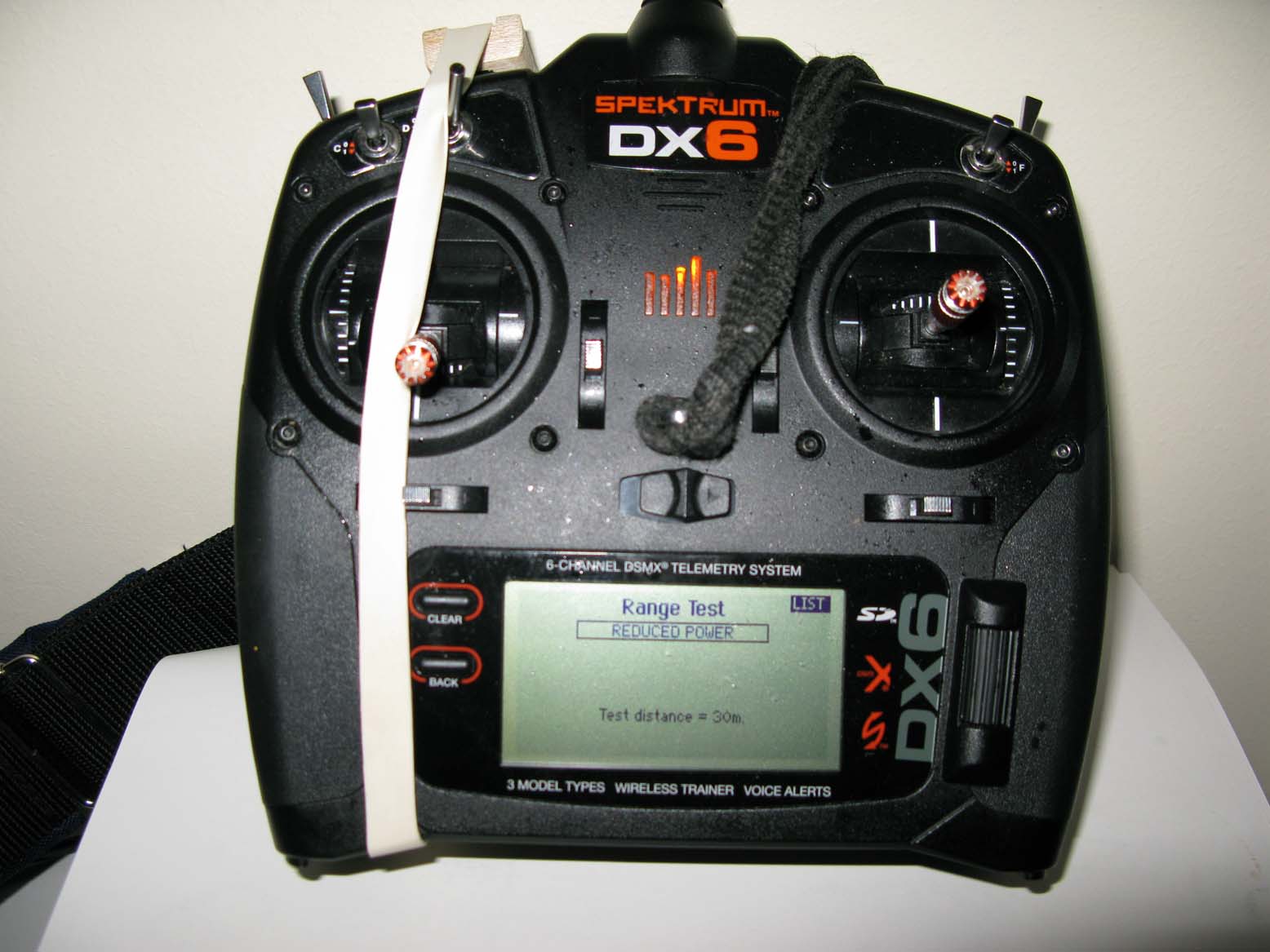
Transmitter banded in Range Test Mode.
Note: When a good result from the Advanced Range Test below is obtained, the Rx should be mounted in the aircraft and the test repeated.
The results should be just as good. If they are not , it means the installation is less than optimum and has caused additional problems.
These must be worked, until the same result is achieved, to be certain you have a robust RF link.
The test needs to be redone with any IC engine running at full throttle with the aircraft properly restrained on the ground.
If you are using a transmitter with a stub, (non foldable aerial), you should run the test twice:
i) With the stub aerial enclosure pointing vertically upwards.
ii) With the Tx lying flat on the table with the stub aerial enclosure pointing axially towards the model.
If test i) has a good result but test ii) has a bad result, it would mean the secondary transverse antenna, which is normally mounted in the case handle is either not working, or in certain Txs absent.
| Step | What | Why |
| 1 | Power up the Tx. | Best power up sequence. i.e. Tx first. |
| 2 | Equip the Rx with a throttle servo and Spektrum Flight Log if used. | Note Spektrum's 2.4 GHz, SSFH equipment is only used by way of example here. The test protocol can be used effectively with any equipment but will need a little adjustment to the steps to suit other manufacturer's equipment. E.g. method of telemetry etc. |
| 3 | Power up Rx. | Best power up sequence. i.e. Rx second. |
| 4 | Bind Rx to Tx | If not already bound, bind the TX/Rx equipment pair. |
| 5 | Band the Tx Range test button as in the photograph above. | The Advanced Range Test involves a separation of 100 yards between Tx and Rx. To facilitate this, the Tx's range test button needs to be banded on whilst radiating reduced RF. |
| 5a | Mount the transmitter on a small table at the flying site with the Tx's antenna correctly orientated towards the aircraft or test board as the model pilot increases the distance between them . | It is vital that the deadspot which occurs with all single folding aeriel Transmitter types is not pointed at the aircraft or test board as this will badly affect the results. |
| 6 | Check Failsafe is set up correctly. | With the Tx's thottle stick forward, (i.e. full throttle), turn off the Tx. After a second or so the throttle lever on the throttle servo should move to idle position. Correct failsafe operation is needed to allow visual recognition of a failsafe event, as this enables the test to be carried out with other OEM's equipment, which may not be so generous with essential telemetry data. |
| 7 |
With the failsafe working correctly, set full throttle i.e. move the throttle stick fully forward to command full throttle. (Note: If the aircraft has an electric power train, remove the propeller and set a modest RPM so as not to damage the motor. e.g.100 RPM. Activation of the failsafe is now visible to the user by the motor stopping running) |
This position of the throttle servo allows the person carrying out the test to visually see if a failsafe is issued by the Rx. (i.e. throttle servo will move to idle.) This means the test can still be carried out without the Spektrum Flight Log or other telemetry systems if needed. |
| 8 |
Walk out to 100 yards, maintaining line of sight with with the Tx and rotate the Rx board in three planes, for approx 7 minutes. (For Spektrum Users Only):While doing this search for any critical orientation angles which will manifest as accumulating antenna fades on the telemetry in use. |
a. Seven minutes simulates a flight. aa. Critical orientations are easy to find, and are expected, as there will be orientations of the test board where RF blocks or Reflected RF Signal Fades occur worst case. |
| b. Rotating the test board simulates the blocking and reflection events which will occur in normal flight, e.g. battery and/or engine etc., causing reflections to arrive at the Rx antennae at the the same time as the data stream which is direct, but 180 degrees out of phase. | ||
| c. It is necessary to maintain line of sight be tween Tx and Rx at all times, as any shading event, such as the tester's mobile phone could throw a failsafe event in reduced RF mode and so confuse the results. | ||
| 9 | Return to the Tx and remove the flight band on the Tx's range test button. | This step is important. If you fail to do this and then power cycle the Tx, you will unbind the Rx by forcing the bind process. |
| 10 | Read and record the telemetry data. The data should show low antenna fades and frame losses and zero Holds, (or Failsafe events). Note: If telemetry is not available, you are looking for zero movements of the throttle servo back to idle, i.e. a failsafe operation. | Anything other than zero holds represents a failed test. Do not fly. Investigate the failure first, correct any problems, then redo the test until zero holds is achieved. Please note we have seen equipment pass the standard 30 yard range test then fail in the air. Then on running the Advanced Range Test on the ground, the Rx was seen to issue a failsafe at 35 yards, i.e receiver had a fault, which the standard thirty yard range test did not show. |
| 11 | Should you get a Hold, (Failsafe event), establish how bad the failure is by repeating the test nearer to the transmitter, .e.g. 50 yards, then 30 yards. If a marginal range of thirty yards only is found while doing this, DO NOT FLY. | Knowing how bad the failure is, helps you decide whether the failure is bad enough. E.g. 90 yards with no failures is probably good enough. 50 yards is possibly marginal so test in a safe aircraft, e.g a foam glider and repeat the measurements after the flight etc. |
| 11a | Their are multiple ways of checking the Failsafe recovery time. The one given here blocks the RF with a metal sheet, while operating in Range Test Mode: Set up as above then at the one hundred yard point with the Tx banded on, in reduced RF mode, shield the the Rx board with something metallic. | This will force a Failsafe event to be issued and the Rx throttle will move to idle. Remove the metallic object and count in seconds until the RF link is re-established. Failsafe recovery time should be two seconds or less. Anything longer than this is too long and runs a serious risk of damage to the aircraft.(i.e. aircraft hits the deck before control is recovered.) DO NOT FLY. |
| 12 | Return to the Tx and remove the flight band on the Tx's range test button. | Again, if you fail to do this then power cycle the Tx, you will unbind the Rx by forcing the bind process. |
| 13. |
Point 13 is added as an alternative to point 8 above for Spektrum users only. At the hundred yard point, and with the Spektrum Flight Log plugged into the receiver, carefully rotate the aircraft or test board until the the accumulation of antenna fades and frame losses reported by the Spektrum Flight Log reach a maximum rate. Now hold the aircraft in that position for approx. 6 minutes. |
This test simulates a flight in the worst position of Rx orientation to the Tx. Antenna fades will easily reach the counters limit of 999 with this arrangement but Holds should remain at zero because of Tx/Rx diversity. Put another way one of the Rx's antennae is effectively off as it's orientation is in a complete dead spot, whereas the other antenna will be working perfectly. Again, should HOLDS occur do not fly, investigate and address the problems. |
| 14. |
There are safety considerations that need to be considered when carrying out the vibration test. In addition, rotations of the transmitter are not needed. This point, No. 14., is added after considering Adrian Hazeldine's comment below. |
As the vibration test needs to be carried out at full thottle, the aircraft must be securely restrained on the ground, as detailed above. The operator then walks away from the model whilst maintaining antenna line of sight until the engine reduces to idle, indicating a Failsafe operation has been set by the Rx. The distance at which this occurs should be comparable to the first test with engine off. Big differences in the results indicate a vibration problem which should be solved before flying. Note. Rotations of the Tx are not necessary as antenna diversity has already been proven in the earlier part of the test, by rotations of the test board and later the aeroplane, or alternatively by Spektrum users locating and using the worst case orientation found as detailed above. |
Related Article Links:
2.4 gHz. RF link problems 1. New equipment failure.
2.4 gHz. RF link problems 2. Tx/Rx RF link principles.
2.4 gHz. RF link problems 3. Advanced Range Test Protocol.
2.4 gHz. RF link Problems 4. Causes and Fixes
2.4 gHz. RF Link Problems 5. Failsafe Triggered
2.4 gHz. RF link Problems. 6. Failsafe Strategies.
Comments
22/March/2016 Added point 5a transmitter antenna orientation.
22/March/2016 Added the text:
If you are using a transmitter with a stub, (non foldable aerial), you should run the test twice:
i) With the stub aerial enclosure pointing vertically upwards.
ii) With the Tx lying flat on the table with the stub aerial enclosure pointing axially towards the model.
If test i) has a good result but test ii) has a bad result, it would mean the secondary transverse antenna, which is normally mounted in the case handle is either not working, or in certain Txs absent.
23rd. January 2017.
Added the Note. to point 7
Added point 13.
24th. February 2017.
Added point 14.
"When you have the radio gear in the plane and run it at full throttle is the model secured on the ground or do you hold it and move it around through all orientations? I'm just thinking of safety when testing a larger model."
These points are clarified in newly added point 14 in the table above. Thanks Adrian. RRH